Total Pageviews

Monday, July 22, 2019

Rack'em Up! DIY 19-inch (ish) Racks for T&E Equipment


      Necessity is the mother of invention....

  A somewhat similar parallel to this might be "tight spaces are the mother of... cheap alternatives" ?!

  Ok, so we all have this "situation" where equipment we buy starts flooding our workspace until you literally are stubbing you toes against them even getting up from your chair.
  Same thing happened me (the flooding part, not the toe stubbing part) so having observed some narrow  spaces  in my workspace, I decided the best way to organize things would be some (only 2) racks.

  Easier said than done.... My workspace is at the second level of the house, up two flights of stairs, one more steep than the other... also the last set of stairs is this weird spiral thing, so you can imagine a normal 19 inch rack  is impossible to haul  up there.
Huh, should see me hauling VNAs and Optical  analyzers up those stairs... my god, that's a laugh for anyone....

  But I digress. So, why not have a rack in pieces and assemble it upstairs.  Wel, how about I up one on this one...  how about I make my own cheap rack system... OK, cheap-ish.

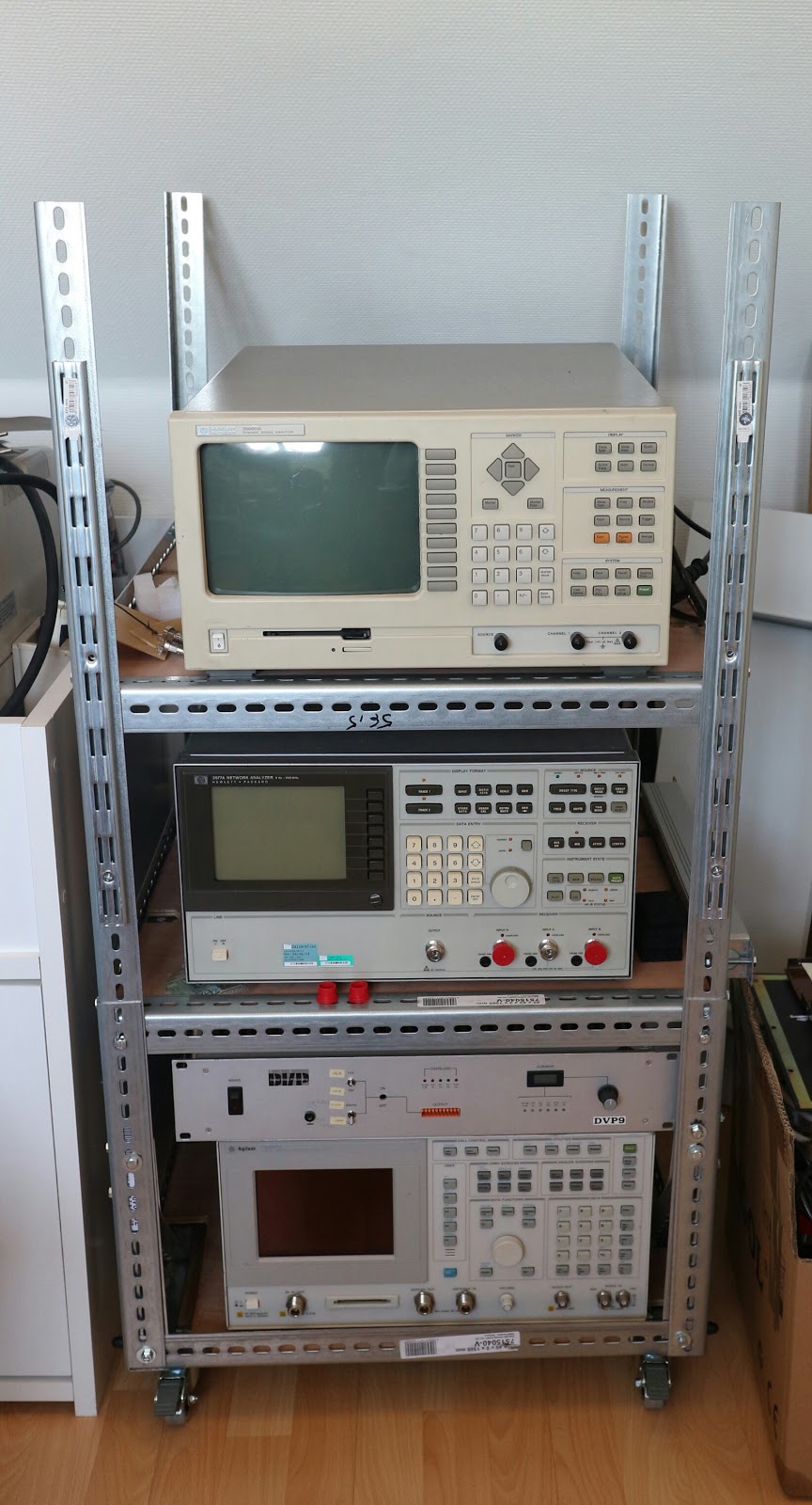
 The big rack, in all its glory

  The structure is made from 2mm thick, 40mm wide angle iron.... A keen eye will see that the dimensions are slighly bigger that the standard 19 inch racks system.. that's because my equipment does not all have the rack handles, so I wanted an wasy way to get my hands on the sides of the equipment to get it in and out of the rack.

  Hence, I came up with these measurements (more out of chance than maths and intent, but hey...) 61.5 cm deep x 56.5 cm wide or 24.2'' x 22.2''
 This is enough so that I can man-handle units in and out of the rack, including big lumbering things like an Advantest optical spectrum analyzer that weighs the equivalent of a medium-sized anvil... and is just as nasty to handle.

  Also, the racks are on wheels so they can be moved around. The big one, though, is meant more to just sit there and look pretty than be moved around. The shorter rack was designed with mobility in mind. Meaning, it's supposed to take equipment that is needed for whatever measurements I'm doing and sit next to my desk. After I'm done, it goes back to it's corner and out of the way.

   The shorter rack I made


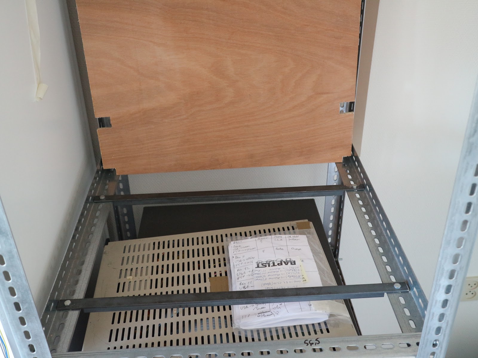
                                The DUT shelf on the mid-height rack, sitting next to my desk. Really                               handy for measuring stuff and having a nice clean desk


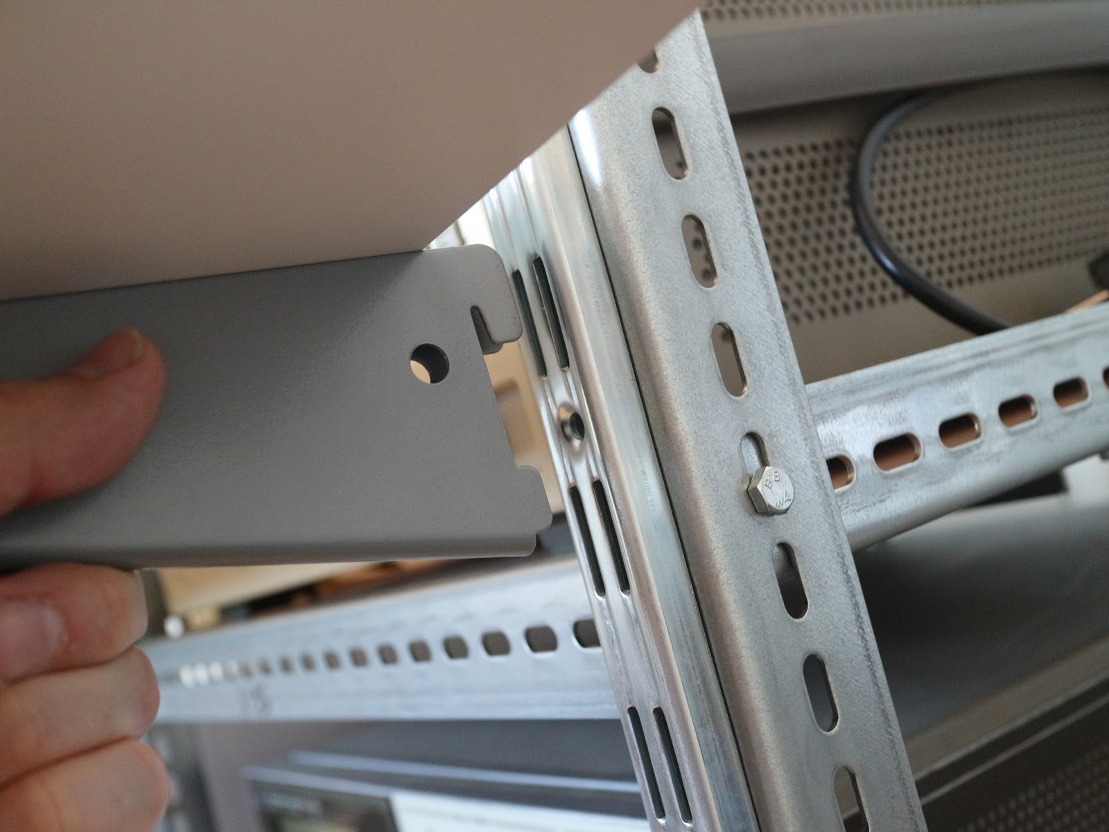
                                             The stand for the DUT with its rackable mount

  And it works pretty well in practice. I also added a nice "porch" for the DUT to sit on when doing measurements or for a scope or whatever else is needed. The "porch" can be moved up or down easily as it has this really nice and fast mating system.

Tell us the price, son...

  So, the tall rack cost about 270 Euros, that's including wheels, all the angle iron, screws (which there's a boat load of), plywood and cross-braces. Ok, I know that there might have been a chance to actually get a cheap 19 inch rack at auction that's somewhere around this price, but because of the logistics of getting one delivered to my home, I just couldn't be bothered. Plus, I made a rack all by myslef... how cool is that.

 Ok, it doesn't look like something you'd write home about, I know.... but considering that the tall one is now holding in excess of 250 kilos of equipment and is stable and still moveable is something to note.
  Price aside, this was also the first rack I made, so once I started building, it took me something like 3 afternoons (as in about 3 or 4 hours every day) and 2 whole days (meaning a Saturday and Sunday) to have everything together and stable. Once I had my head around the whole thing and knew how everything should go together, the second rack took only a whole weekend to cut, screw and assemble.

                                  One of the shelves. Board in the upper part and the two
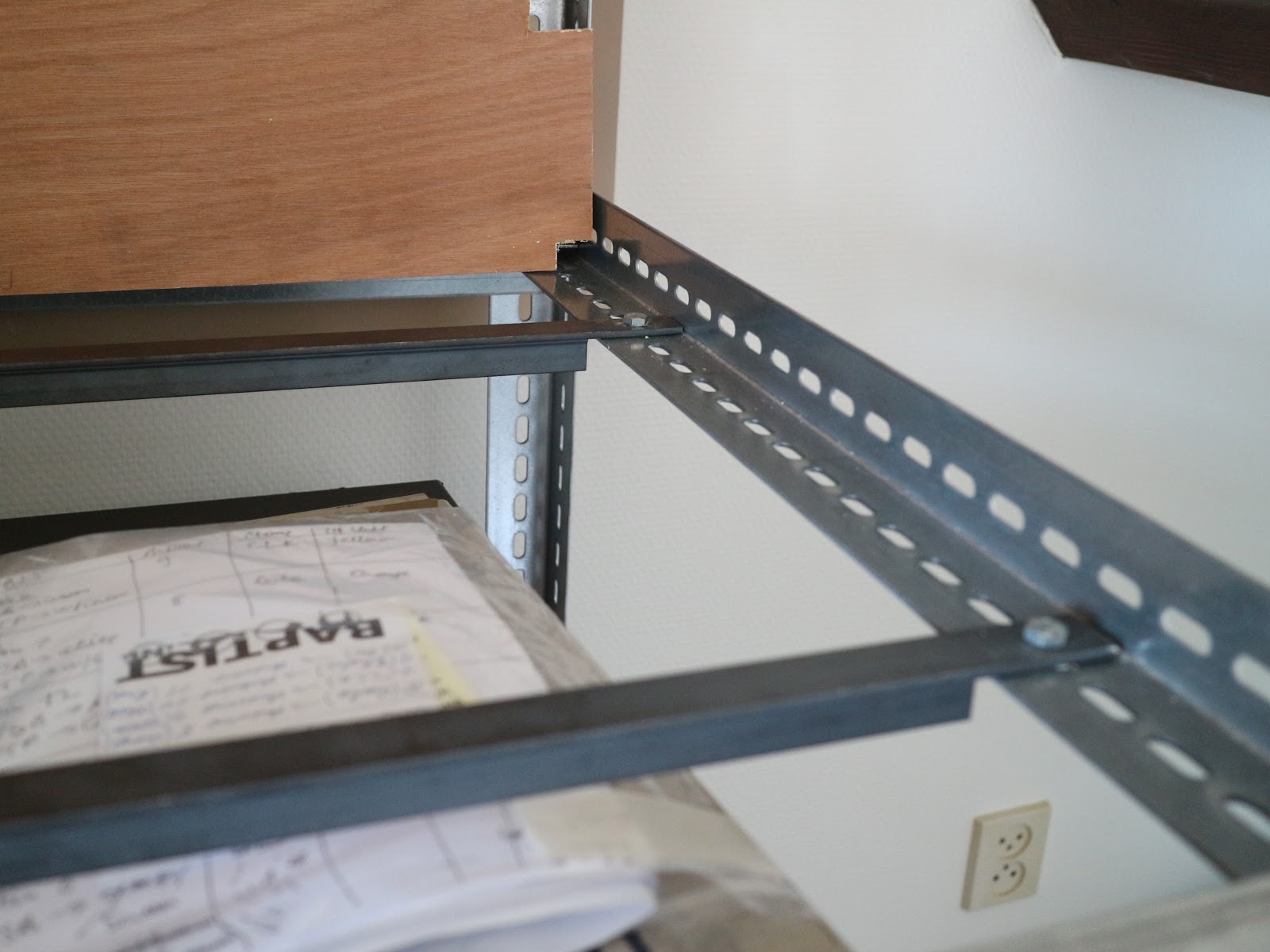
                                               cross braces made from steel T profiles


         Why not those modular aluminium extruded profiles, I hear you ask ?
  Well, turns out that a) they're  kinda expensive and b) it's a real hassle to figure out all the bits and bobs you need to put everything together. For the tall rack, my calculations stopped at around 250 Euros for the 4 vertical legs, wheels and 4 rafters. Adding to that another 150 Euros in things to keep everything together and I started to look for altenatives. The end result may not be as sexy, but it does the job and I get extra "cool" points.

  Hope you enjoyed this and maybe it inspires you to get cracking on your own thing. And if you do, please make it pretier than mine... and share some pics.

Tuesday, July 9, 2019

Counterfeit 3045 low noise LDOs from eBay


    Sometimes lazyness gets the better of me and I tend to look for an easy way out or an easy fix to stuff. Buying ready-made boards from eBay is one such way, but in this case, it ended biting me in the ass.

   I have a project where I want to have some voltage references and other sensitive experiments into an enclosure and also have a really low noise  LDO to power them, in the same enclosure as the rest. I thought that some LT3042/3045 would be ideal. Instead of making my own boards, I thought why not buy some ready-made ones from eBay

                                                    My future-to-be experiment

   So I bought two different boards. One is a really crappy looking one with what can only be desribed as the world's crustyest capacitor. Fun fact.... the blue cathode markers on the rectifier diodes is actually done with a marker or sharpie. How do I know? The marks disappearead after I put a bit of alcohol to wipe away some rosin on the board  :|  


LT3042 board


       Crappy looking input capacitor. It's light as a feather and came already swollen. 

   Crappy looks aside, the LT3042 on this board looks genuine. It has the right markings on the case "LTGSH", which according to the Datasheet , is the right one for the MSOP package. 
OK, so far so good...

   But I needed another LDO. And I wanted another design, just so I can, at some point, try to measure their noise against a real LT3042 board  (which would be designed by me, but somewhere in the future,  or so I thought) and see which one (mine, of course) would come out on top as having the lowest noise.

   I give you specimen no.2, which, after making its way from Saudi Arabia, of all places, it ended up under my attentive (not really) gaze.
 At first glance, looks legit and much cleaner layout that the previous dog's breakfast. But unfortunately the devil is in the details....


                                                        LT3045 board AKA specimen no.2


    On attentively looking at the LT3045 Datasheet  we see that there are two variants of the chip....one with 10 pins in a DFN package and another with 12 pins in an MSOP package. But someone in China was thinking, and, as you can see from the above picture, they decided to do away with LT's wasteful marketing B.S. and just have a  DSN package with all 12 pins on it. Brilliant! 
  Only thing is, I actaully wanted an LDO that really is low noise and something tells me this one is not it.

   I am working on an LNA set-up to measure voltage reference noise and will also try to measure the noise of these boards and compare them to one I will design myself, because there's really no other way to ensure I really have the expected performance.

 
   Bottom line is, when it comes to these low-noise LDOs, 75 percent of the performance is actually in the board design and I am highly doubtful that the ones on sale on eBay are actually designed by someone that gave a sh$%^t about "low-noise". The other 25 percent is actually getting a chip that is the real deal. So just be careful what you buy and hopefully I made you wary enough so that you don't waste your money on useless junk.


Hope you found this info useful. 

Have fun with your projects

Monday, April 1, 2019

Toshiba Ultrasound Machine Part 2: Ultrasound Probe Teardown

      You might have seen Part 1 of my Toshiba Ultrasound machine  post, where I did a teardown of a Sonolayer SAL-32B  and also explained the basic physics that goes into turning sound into images.

    One thing I couldn't really do was to also take apart the probe. That's because it would have been a destructive teardown and I still wanted to play around with the thing.
  But now, the teardown gods have  blessed me with two other Toshiba probes, one of which is very similar (i.e. same connector but the mating is a bit off) therefore, I'm going to cut one open and actaully see what's inside and how the arrays are mounted.

   Key note here.... this is 80's, early 90's tech we're talking about, so some technical aspects may have drastically changed in the new generation probes. (Yes, this is a hint to anyone with access to a modern probe to also perhaps post some pics of the insides of one)


Figure 1. The probe in all its glory

   I actually got two probes, this and a cavity probe. So yes, no  expense was spared when hosing the probes down with the germicide. Now, it's time to get the tools out.


Fig.2 Probe connector


  The casing around the connector is pretty easy to take off. Just a few screws...


Fig.3  Just like Fig.2 except in more pieces


  There seems to be some colour coding to the wires... white blue, red and the ground and shield. Will maybe have to see later in the probe head how they're connected.


Fig. 4 Probe connector wiring. Also, the 4 black wires seem
 to perhaps code some settings for the
 ultrasound machine? Probe type or other atributes?

  Now time to take care of the other end. The plastic itself is a bit weird, in that it's fairly soft and elastic. Once inside, you can aleady see that everything is potted :|
 Technology, am I right...


Fig.5 Probe head. Cry havoc and let slip the
 flat-blade screewdriver. 


  Of course, the potting makes sense. One has to attenuate any signal also emitted from the back of the piezo element.


 Fig. 6 Probe head elements

   As in the drawing  above,  you can see the "Acoustic Insulation", in this case the potting compound in the probe head, filling up all the space behind the piezo elements. It's dense and rubbery and kind of a PITA to get through. Exactly what you'd want from an RF and sound dampening material.


Fig. 7 Probe head cracked open. Black stuff is the actual potting compound. 
The black stuff on the outer plastic is conductive

  And of course, the name might be "ultrasound" but we're still talking low-frequency, low amplitude RF here. 1-10 MHz, so of course there's also copper shielding around the whole probe head. 
  The potting compound isnside the probe is not conductive, however, on the inside of the plastic casing there is a thin deposit of conductive material...carbon maybe?


Fig. 8.  Just in case nobody believes me it's conductive...

   On the front of the probe there seems to be a plastic casing or bezel, together with even more copper shielding underneath.
  As a side note, the copper shield is pretty thich stuff. It kinda feels like 35um copper clad thickness. And no, no blood was drawn for the teardown gods.

Fig. 9 Probe head...head. Plastic bezel and some more 
copper shielding visible beneath the bezel.

Fig. 10 Probe head: Black shiny thing is the back of the  piezo element 
backing material


Once the bezel is out of the way, the potted body and the actual probe head come apart, connected only through some  flex PCB material. 

The black glossy stuff you see in the pic above is actually glass (just normal, perhaps tempered  or borosilicate glass). This would be the "Backing Material" from Fig.6


Fig. 11 Probe head, front view. Flex strip, piezo elements 
(brown thing) and rubber face (white thing)

    The actual piezo elements, in their full glory (that would be the retangular brown thing). So, the wires come in on a PCB flex board then that goes out to every piezo element. The white thin plastic on the front (the one partly cut off) is some kind of rubber or silicone, with probably some stuff in it. It felt grainy when cutting it with a blade.


Fig. 12 Probe head side view

   So there's a bit more going on in the probe head than I initially thought. The piezo elements are backed by a rectangular piece of rubbery epoxy with  probably tungsten carbbide powder and then, behind that, the piece of glass from Fig. 10.


Fig.  13 Flex PCB connection to piezo elements (Top. left and right) 
and Piezo elements themselves (Bottom)


   Here you can see how the connections are made to the individual piezo elements. Each wire from the probe connector (Fig.2) comes in onto a small PCB (Fig. 14) with 330R resistors connected to Ground and then go further to the flex strip which then connects to 4 piezo elements (Fig. 13, Top, left and right) At least that's my assumption.
  The return from the piezo elements seems to be common and of course split into two groups, just like the PCB with the 330R resistors.


Fig. 14 Main body of the probe head and PCB with 330R resistors

   I don't know if this is to better achieve beam forming or it's because of how the actual hardware part works. This will require more investigation on the machine itself to find out. Also, because of the potting, I couldn't really figure out the meaning of the blue, white and red wires.
  And no, I didn't manage to count all the traces on the flex PCB. After loosing track 2 or 3 times, I just gave up on this.

If someone more knoledgeable about this can share some info, he's welcome to do so in the comments, below. Thanks.

   I've already started reverse engineering some things on the machine side of things and got some scope shots, but I need to probe around more to get a feel for what's really going on in there. 
  Also, because of ground loops, and not knowing how the architecture of the thing is layed out, I'm hesitant to poke my probe willy-nilly, so until I'll design a 1:1 differential probe, things won't progress much.

     That's it fow now. As always, you can find all the pics from the teardown in the albun located here.


Sunday, February 10, 2019

Keithley 7013-C relay card headless operation

    This will be just a quick post of one things I've been woring on. I have a lot of stuff on the back-burner and about 4 or 5 really interesting blog posts that await to be written up. unfortunately there's a lot of work that has to go into the experiments for those, so bare with me.

   Now that I've made my excuses, here's what I came up with, for using a Keithley 7013-C relay card as standalone.


   It's not that  complex, but it kind of took a lot of time just because of the metric ton of soldering I had to do on the LEDs and wires and also because the modifications to the existing equipment was quite complex. A lot of cutting, filing and drilling... you know, the fun stuff

I got this relay card really cheap but don't have the Keithley DMM for it. It's for a Keithley 7001 Mainframe scanner, but I don't have that neither do I want to buy it. So I decided to put together a platform that allows me to take advantage of the realy card and use it to take measurements of....well, electrical stuff.

   For those curious, you can find all the specifications and schematics in this link.

  The guts of the card are pretty simple. Three  serial shifters, UCN-5841A and, of course, the relays.
   Keithleys are strange beasts, so together with the normal 5V DC supply, there's also a 14.6 V and 6 V rail.... go figure. Nothing some LM317s can't handle.
Note to self... make sure the voltage diciter on the LM317 meets the minimum current load (~10 mA works best).

  The unwilling donor is a piece of  old 19 inch rack mount Philips video equipment. The card slots are almost the right length to fit the relay card in. Almost...
Which in home-gamer talk, that's "take out your rotary tools".

  The front panel was the first to get the make-over.


   I gutted the donor, took out one whole card and took off the components from a second one, so that I could use that as a platform for the miscellaneous stuff I needed (wiring, power supply). I also made everything as modular as possible, with connectors everywhere, so in the future, if I get any more bright ideas I can implement them quite easily.....that, and it makes sense to quickly undo connectors instead of hard soldering stuff together, in case of some unhappy misshaps.


    The transformer secondaries were made for 12V DC operation, so I had to series two of them for the 14.6 V DC rail. Not ideal, but the current demand isn't that high so there should be minimal power dissipation. After about 30 or 40 minutes of playtime with the thing, turning relays on and off, none of the linear regulators got warm, so I guess my hunch was correct. I also did multiple 12 hour runs and everything is still OK. Even a blind dog gets lucky sometimes...

   Those LEDs on the front panel that I showed are to have a visual guide of which relays are doing what, so I also modified the card  itself and added a connector and wires to the shift register outputs. 


Remember kids, 5 minute epoxy might seem handy, but it's a piece of crap. Don't use it. Use the normal epoxy. 5 minute epoxy has a tendency not to stick well and just ruin everything afterwards. Either that, or use Araldite epoxy.

   And of course the drivers for the actual LEDs:


  I organized the whole thing in 2 rows, 10 LEDs each. The botton row is attached to a big PCB that also has the hex buffers on it. The upper row is just stuck on a small piece of protoboard and a ribbon cable going from that to the other board.


   I used a plethora of hex buffers, basically what I had lying around. I think it was two 74LS04, one 74LS19 and something else I don;t remember right now. I'm not really picky, as you can see. Anything goes.

    Of course, nothing is as simple as it looks. The relays are wired in what might seem to be a weird way to the shift registers. For example,  outputs 1 to 4 on the last shift register are wired to channels 1 to 4 but outputs 5 to 8 are wired to channels 8 to 5. So basically the second nibble (last 4 bits) in the first byte (order is LSB to MSB) are reversed. This also goes for the other two shift registers. Confusing? Here's something to help explain  it better


  Also, just a quick mention.. with so much wiring flopping around in the breeze, I used ETFE/PTFE  insulated wire, because it's a given that at some point you'll touch some wires with your soldering iron. It saved me a lot of headaches, let me tell you.

   The controller software, running on an Arduino, is not necessarily the best, in terms of efficiency, but it gets the job done. There's two main parts to the whole thing:
 - The input command handling part
 - and the actual data output to the shift registers

The command handling part isn't really SCPI standard, but I thought this is the easiest way to implement. Strings on  Arduino isn;t the simplest thing to get working well.

A command can be either for a single relay:
2=ON;

or multiple commands
2=OFF;3=ON;

The ";" at the end of a command is a must, in either of the two formats. The SW doesn't throw  back invalid format errors (yet) but nothing will happen if the romat isn't right (as far as I know)

The data to be shifted to the SW is first decoded from the input command, then stored in an array,  Relay_ch[]. From here, because of the way things work with these shift registers, the data gets switched arround into Relay_ch_toSend[] the finally out of the Arduino;

For the actual signals that go to the registers, this si how it happens:
  Data pin set either high or low, depending on whether  Relay_ch_toSend[] is a 1 or a  0. Then a clock pulse is sent in order for the data to be input to the register's register. (I actually  meant to write this)
Once all the desired serial data is loaded, a Strobe pulse will load it into the output latch register and then, pulling Enable low will activate the outputs of the registers.

   Because the PC needs to interface with mains-connected equipment, I've isolated the digital lines using some 4n25  optoisolators. The turn ON time of these is quite OK, but the turn-off...well... let's just say that the Arduino waits around a lot, in software. Hence thosewait times in the software in between switching  the data and clock lines.

  The first test I did was to measure the leakage of 5 wet tantalum capacitors with my Fluke 8505A. Probably the relays are not too well suited for this, but the results are more or less consistent. Did 3 12 hour test runs, after the caps were  formed @10V for at least 24 hours and both the Arduino and Keithley relay board behaved flawlessly.

As always, this is the link to the pics I have for this project. Enjoy


Wednesday, October 17, 2018

Edwards E2M12 Vacuum Pump Teardown and Overhaul

   High vacuum is one of those things that really suck.... Sorry, couldn'd help it. 
  Parts are expensive, finnicky and not always readily available to anyone.


    I recently bought an Edwards E2M12 vacuum pump for a project of mine. When I got it, it came without any oil and without any idea of the state it was in. But for the money I paid, I couldn't just pass it.


   So, I now have a vacuum pump... what now?


Well, to be able to make it suck in the proper way, I needed to give it an overhaul So first thing's first.. get an overhaul kit. How hard can it be?

  Well, very hard, apparently, unless you're a company. Very limited opportunities for those of us not blessed with a VAT number.
Most of the suppliers out there, including Edwards themselves only sell to companies and the only source for the kit I found, charged a hell of a premium for it and asked a metric ton of money for shipping something that weighs in a couple of hundred grams.


As reference, here's a list of stores that have Edwards supplies and kits, together with my rants comments


  • www.vacuumpumpsupply.com This is where I bought my kit from. A bit over-priced, but hey....at least they sold me one They do deal with individuals, not just companies, so that's perfect. However the shipping was very expensive even from the USA to Europe. Also, 0 points for customer support. I litterally tried calling them tens of times but nobody answered. Also all my emails sent to them requesting some info about the order went unanswered. But hey, they don't need to answer any phones or mails when they get a wad of money from their customers

  • www.idealvac.com Yep, they also have kits and yes, they do do business with individuals, but they're even more expensive than the previous guys.And shitty shipping policy. If you're from the US, they're...ideal. If not, tough cookies then.

  • https://shop.precisionplus.com  European store from what I can figure. Pretty low prices, but they only deal with companies. Only found out after about a week of trying to get someone there to look into why my account was not active. Though if you can borrow a friend's VAT number, they have the lowest prices as far as I've seen.

  • https://www.jrtech.fr/en/  A lot of supplies  here. Regarding my kit, they only had it from some off-brand company. Not original from Edwards. Could be helpful in a pinch, though.


    Was wondering what happened to all 4 of my mails and the 10+ phone calls or so. But the EM12 kit is finally here. Now what?


  Well, easy if you know you way around one of these things. Not so much if you're a noob like me. So, we seek the help of the collective hive mind.


   This helped me out a great deal. Nice write-up, and a lot of other useful links and info in the posts. Seeing how many models of these vacuum pump are out there, I thought I'd post my own adventure together with some helpful pics. Be sure to have a look through all the posts on the  EEVBlog link before you start working on your pump.


    First thing's first: flush out the pump. That is, drain whatever  oil there is in the pump then fill it with some cleaning fluids. Paint thinner is recommended in the link above, but I couldn't find anything useful, so I used some denatured alcohol. It doesn't do a great deal to dissolve the oil but it does flush out any dirt and in my case, spider webs and is safe on the seals. Of course, the E2M12 is well made and no ball bearings inside to screw up with aggressive solvents. But I went the safer route.


   Yep, guessed it... the blue stuff... denatured alcohol. Even after this step, there will still be oil left if you plan on tearing down both stages of the pump So have a lot of rags on hand or have a big sheet of plastic on your work table / space. I had a big plastic tupperware lid on the table, so it'd catch any oil spills.


Next step would be to get some service manuals for the pump. You can also find those in the previous link. As a side note, the M2, M5, M8 and M12 are functionally the same.


    If you plan on taking this thing apart, make things easy. Separate the motor from the pump first. This will make everything much easier when handling.  Start with the two red plastic parts either side of the pump.

On mine, the coupling to the motor  has two keys on either end of it and two grub screws (#1 and #2 in the pic below) Undo both of these and then the four  Allen bolts holding the motor to the pump's frame.


    Then you can just pull the motor away from the pump. 2 people are ideal for this task, but being the proud engineer that I am, and also being alone in the house, I did it by myself. 

My pump didn't come with a plate underneath. If yours has this, also undo the bolts holding the motor to it.


    Putting aside the motor and focusing on the pump itself, undo the four allen bolts holding the pump cover....after you've drained everything from the pump, that is.


You can use a plastic or wood shim to pry the two halves apart.


   Now that you're in like Flynn,  how about you take off that thin steel plate held with those two allen screws.


    And, while you're at it, undo the other two and the small aluminiun block holding that copper pipe (gas ballast tube) in place. Slide the cast rear cover plate down about 1 or 2 cm and slowly but firmly pull on the pipe. It comes out easily, just be sure not to bend it too much. 


Once the plate is off, you have access to one of the pump's stages.


    If you want to go ahead and take out the vanes, a word of caution. They're made out of some kind of phenolic resin so do not grab then in any way. Handle them like you would one of your french girlfriends.  
   I, on the other hand, took a dental pick and pried them out by hooking onto the spring inbetween the vanes. Another way to do it is also mentioned in that link from EEVBlog... take out the screws holding the pump stage (LV stator) to the rest of the body and slide it out a bit. 1 cm should do it, then push it back in. This should expose the vanes just enough so you can get them out.


Sources mention there is also a bolt in the middle of the now exposed shaft. Mine didn't have something like that. Seems they modified the design through the years.

 So all I had to do to get to the next stage was to only undo the allen bolts of the LV stator. The alignment to the main body is ensured by two precision ground  pins. Easy, right?
Well, it depends. This is the actual tricky part of the whole thing. The mating surfaces of the two parts are machined and can actually stick together.


    There's two recesses in the pump body, one on each side (marked with yellow). You can use those to prie open the parts. Just don't do it with metal tools; use plastic, wood or like I did, aliminium. Even with the aluminium I was extra careful not to scratch the inner surface of the parts. And used them only up untill the point the plates were separated enough to allow some plastic shims in between them.

    Also, the guide pins (marked in...yellow?...lime green?) will ensure the plate jams if you do not pull it out  straight


    These are some of the tools I used  in taking apart the plates. And yes, that's a PCB you see there. I filed down one corner thin enough to get in inbetween the plates and spread them apart. The orange shims were also used fot this task to take over where the PCB left off.


    At this stage, my pump looked pretty clean, so I didn't go any further. I just replaced the seals and started to put everything back together again.


    Also note that there's a lot of service manuals from Edwards from different years and the actual numbering on the schematics is not the same, only the names of the items. So be careful if someone refers to parts from schematic numbering instead if actual part numbers.


A few O-rings and some tightened screws later, everything was back together again.


  Oh, yeh.. you might have noticed the Edwards Pirani gauge on the pump. A little something I picked up on eBay. Works too... imagine that. It's an APG-M gauge and like the pump, it has its own story. But I'll tell that somewhere more private. Like in a next post.


    All's well when it ends well....ish..

 I measured the vacuum level after I put the pump together and the fact that it make any is a real surprise to me. Looks like I'm not all thumbs. But it barely makes 1 x 10e-2 mbar, which is OK for now, but way under the expected performance of this pump.
I think I narrowed it down to some leaks in the gas ballast circuit... probably didnt istall that allast gas pipe correctly. I'll get some vacuum grease and put a dab on the orings and will post some updates. 

As always, this is the whole album of the teardown. Enjoy


google-site-verification: googlee8a41f51abde7545.html